

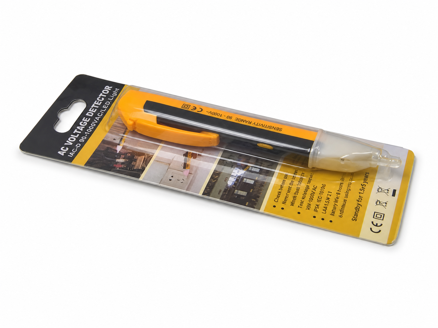
The wire is disconnected, it is not connected to anything at either end, and the tester still lights up. Nothing is wrong with the tester and nothing is wrong with the wire: a conductor that runs alongside a live one is capacitively coupled to it, and the voltage that develops on it is real. What is not real is the current behind it — the coupling can produce a few microamps at most, which is enough to drive the high-impedance input of a non-contact tester and nowhere near enough to do work. The practical rule that follows is short: a non-contact tester tells you a conductor should be treated as live, and it can never tell you a conductor is dead. The VD06 and the other testers in our range are built to that rule, and this page explains the physics behind it.
Everything here is standard electromagnetic theory as it applies to test instruments. Wenzhou Zhengyuan Electronic Co., Ltd. builds the testers and multimeters named below in its Wenzhou factory.
What the Tester Is Actually Sensing
A non-contact voltage tester has a sensing electrode in its tip and no galvanic connection to the conductor at all. The tip and the conductor form the two plates of a capacitor, with the conductor’s insulation and the surrounding air as the dielectric. An alternating voltage on the conductor drives a small alternating current through that capacitance into the sensing electrode, and the instrument’s input stage turns that current into the beep and the light. Two consequences follow directly from the fact that this is a capacitor and not a connection. The current is proportional to frequency and to capacitance — at 50 Hz a few picofarads of coupling yields microamps, not milliamps. And the sensitivity depends on how much capacitance there is, which is why the same tester responds differently to a conductor held in open air than to one lying against a live cable.
The other half of the circuit is the reference. The tester needs a return path for that current, and it gets one through the user’s body to the surrounding environment. This is the reason a tester’s indication changes when you change how you are standing: gripping the body firmly rather than touching it with a fingertip increases the coupling to your hand, and standing on an insulated floor or wearing insulating gloves reduces the return path and makes the instrument less sensitive, not more. It is also the reason two-pole testers exist, in which the return path is a deliberate lead rather than a person.
Why a Disconnected Conductor Still Reads as Live
Take an isolated length of cable that has been disconnected at both ends and run it parallel to a live conductor for a few metres. The two conductors are coupled to each other by capacitance, and the floating conductor is also coupled to everything around it — conduit, structure, earth. Those two capacitances form a divider, and the voltage that appears on the floating conductor is the live voltage multiplied by the ratio between them. In a typical installation the coupling to the live conductor is small and the coupling to the surroundings is comparable, so the voltage that develops can be a substantial fraction of line voltage while the available current stays in the microamp range.
That combination — a real voltage with no energy behind it — is what a non-contact tester is designed to detect, and it is why the instrument cannot distinguish a conductor held at 230 V by a low-impedance supply from one held near 230 V by nothing but capacitance. Both look identical to a high-impedance input. This is the phenomenon known in the trade as ghost or phantom voltage, and it appears most often where cables run in long parallel groups, in the same conduit as live conductors, or in metal containment that itself sits at a potential.
The Test That Settles It: Load the Conductor
The measurement that separates a live conductor from a coupled one is to draw current from it deliberately. Connect a load across the conductor and a known reference, or use the low-impedance setting on a multimeter, and take the voltage reading again. A conductor held live by a supply will keep its voltage, dropping only by the amount the load draws. A conductor held live by capacitive coupling will collapse, because the coupling can supply microamps and the load asks for milliamps or more. That collapse is the proof.
A multimeter with an NCV function and a Lo-Z range does both steps in one instrument, which is the combination on the XT802 and the DT6222: sweep the conductor without contact to find out whether it needs attention, then confirm with a loaded measurement before you put a hand on it. The two functions answer two different questions and neither one replaces the other.
False Positives: Sources of Coupling You Will Meet
Parallel runs are the common case, but they are not the only one. Electronic drivers and dimmers produce switching waveforms with high-frequency content, and because the coupled current rises with frequency, the harmonics that a driver puts onto its wiring couple far more strongly than 50 Hz mains would. Variable-speed drives do the same on the motor side, where the waveform is a fast-switched approximation of a sine wave. A tester held near a fluorescent fitting’s wiring, or near the cable to a load that is being dimmed or speed-controlled, will often respond when nothing is live. Proximity effects matter too: a tester touching the outside of conduit that contains live conductors may respond even when the conductor you are interested in is not the one it is hearing.
None of these are faults. They are the instrument behaving as designed on the signal present, and the answer to all of them is the same as the answer to ghost voltage — confirm by loading, or confirm by contact through a meter rated for the location.
False Negatives: When It Stays Silent on a Live Conductor
The dangerous failure is the opposite one, and it has more causes than operators expect. Earthed metal conduit or armoured cable shields the conductor, and the capacitance between the conductor and the earthed screen is much larger than the capacitance to the tester’s tip, so the divider puts almost none of the voltage where the instrument can see it. Thick insulation has the same effect by geometry. A tester with a weak battery can lose sensitivity gradually, without any indication that it is degrading until it stops responding entirely. And the return path through the operator varies: gloves, insulated footwear and an insulated floor all reduce it, which is how the same tester produces different answers for two people checking the same conductor.
The general lesson is that a silent tester is not evidence of a dead conductor, and should never be treated as such. Its silence means only that this instrument, held this way by this person, is not detecting a field at this distance under these conditions.
Where NCV Belongs in a Safe Working Sequence
Non-contact detection is a first pass, and it belongs at the front of the sequence. Its value is speed and reach: it tells you whether a bundle of conductors warrants attention before you open anything, it works through plasterboard and insulation where a probe cannot go, and it can sweep a group of cores faster than any contact method. What it cannot do is give you permission to touch. The proof of isolation is a contact measurement of voltage on the conductors themselves, made with a meter rated for the category and voltage of the location — the guide to tester types and safety sets out which instrument suits which location, and the CAT rating article explains why the rating on the meter matters more than the reading it displays when the circuit is live.
Used that way the two techniques complement each other without overlap. The tester answers whether a circuit needs attention; the meter answers whether it is safe to work on.
Tell Us the Conditions You Work In
The behaviour described here varies with the instrument as well as the installation, and sensitivity is a design decision rather than a single figure: a tester tuned to detect weakly coupled conductors is by definition one that will also respond to interference, and a less sensitive one will be quieter and will also miss a screened conductor. Which trade is right depends on the environment the tester will be used in — domestic wiring, industrial panels, drive-heavy installations — and on whether the operator works alone or alongside a second instrument. Order a sample and try it on an installation you know: a live conductor, a disconnected one running alongside it, and a cable inside earthed conduit, and see which of the three your current tester gets wrong. Then send us what you found, the installations your customers work on and the quantity you are planning. Our Wenzhou engineers reply within 24 hours and quote per-unit pricing once we have your numbers.