

What a Diode Test Reading Actually Tells You
The diode position on a multimeter does not measure resistance. It pushes a small current through the junction and shows the voltage that appears across it, in millivolts. A healthy silicon diode reads somewhere between 0.5 and 0.7 V one way and OL the other way. That single pair of readings answers four questions at once: whether the junction conducts at all, which way it faces, whether it is shorted, and whether it is open.
Most of the confusion around this position comes from reading the number as a quality score. It is not one. A diode that reads 0.62 V is not better than one that reads 0.55 V, and a diode that reads 0.30 V is not half as good. The number identifies the part and the material it is made from, and the pair of readings in both directions identifies whether it still works.
Our Wenzhou factory tests incoming diodes on the same bench where the finished meters are calibrated, and the mistakes we see are the same three every time. Someone treats OL as a failure when it is the correct answer, someone treats a low reading as a short when it is a Schottky part, and someone uses the continuity buzzer because it is one click away on the dial. All three are avoidable once the display is read properly.
Why the Diode Position Reads Volts and Not Ohms
In resistance mode the meter applies a voltage and works out the current that flows, then divides one by the other. That works for a resistor, which behaves the same in both directions. A junction does not. It conducts in one direction and blocks in the other, and the relationship between voltage and current is exponential rather than linear, so a single ohm value would describe nothing useful.
The diode position avoids the problem by reporting the forward voltage directly. A typical handheld meter supplies about one milliamp into the junction and allows the display to rise to roughly two volts before it gives up and shows OL. That compliance limit is the single most important thing to know about the mode, because it decides which components can be tested at all, and it is covered further down.
Reading the Display in Both Directions
The test is always a pair of measurements. Put the red lead on the anode and the black lead on the cathode, note the number, then swap the leads and note what happens. Red is the positive side in diode mode on almost every meter, which is the opposite of what many people assume after years of using the resistance ranges. If the meter has a dedicated diode symbol on the dial, the display is already set up for this.
Direction one tells you the forward drop. Direction two tells you whether the junction blocks. A part that conducts a little in the reverse direction is leaking, and a part that conducts fully in both directions is shorted. The table below is the whole decision tree, and it covers ordinary rectifiers, small signal diodes, Schottky parts and LEDs.
The Reading, the Junction and the Next Step
| What the display shows | What the junction is doing | What to do next |
|---|---|---|
| 0.500 to 0.700 V one way, OL the other | Silicon junction, forward biased and blocking in reverse | Part is good, reading is normal for a rectifier or small signal diode |
| OL in both directions | No current flows either way, the junction is open | Replace the part, or check that the leads are actually touching the metal |
| 0.000 to 0.050 V in both directions | Current flows freely both ways, the junction is shorted | Replace the part, and check the circuit for the fault that destroyed it |
| 0.150 to 0.400 V one way, OL the other | A germanium or Schottky junction, lower forward drop by design | Part is good, compare against the datasheet rather than against a silicon diode |
| 1.600 to 3.400 V one way, OL the other | A light emitting diode, forward drop set by the semiconductor material | Part is good if the meter can reach that voltage, see the next section |
Read the fourth row again. A Schottky diode that reads 0.25 V is not faulty, and it will be ordered as a replacement for a 0.6 V part by anyone who compares the two numbers without knowing what they describe. The forward drop is a material property. Silicon sits near 0.6 V, germanium near 0.3 V, and a Schottky barrier sits between the two depending on the metal used.
Why a Good Diode Can Show OL
OL on the diode position means the meter could not push enough voltage to make the junction conduct. On an ordinary silicon rectifier that never happens at one milliamp, because 0.7 V is well inside the two volt ceiling. On an LED it happens all the time. A red LED needs about 1.8 V, a green one about 2.1 V, and a blue or white one between 2.8 and 3.4 V, so a meter whose diode test tops out at two volts will report OL on a perfectly good white LED.
The way to tell the difference between a lamp that is open and a meter that has run out of headroom is to test the same LED with a meter that has a higher compliance, or to put a 3 V supply and a series resistor across it and see whether it lights. If it lights, the junction is fine and the earlier OL was a limit of the instrument rather than a verdict on the part.
The same ceiling explains why some diodes read low and unstable on a cheap meter: below the point where the junction turns on, the display is showing leakage and noise rather than a forward drop. A number that crawls between 0.1 and 0.3 V and never settles is usually a sign that the meter is starved of voltage, not that the diode is marginal.
Continuity Mode Is Not a Diode Test
The buzzer is convenient and it is the wrong tool here. Continuity mode applies a low voltage and beeps below a fixed resistance threshold, usually somewhere between 20 and 50 ohms. Many meters beep in one direction through a silicon junction and stay silent in the other, which looks like a test but tells you almost nothing about the forward drop, and nothing at all about reverse leakage.
Worse, a beep in both directions is ambiguous. It can mean a shorted diode, or it can mean a diode in parallel with a low value resistor or a transformer winding, which is exactly the situation on a populated board. The diode position at least gives you a number you can compare with the schematic or with a known good part, and a number survives a second opinion from a colleague.
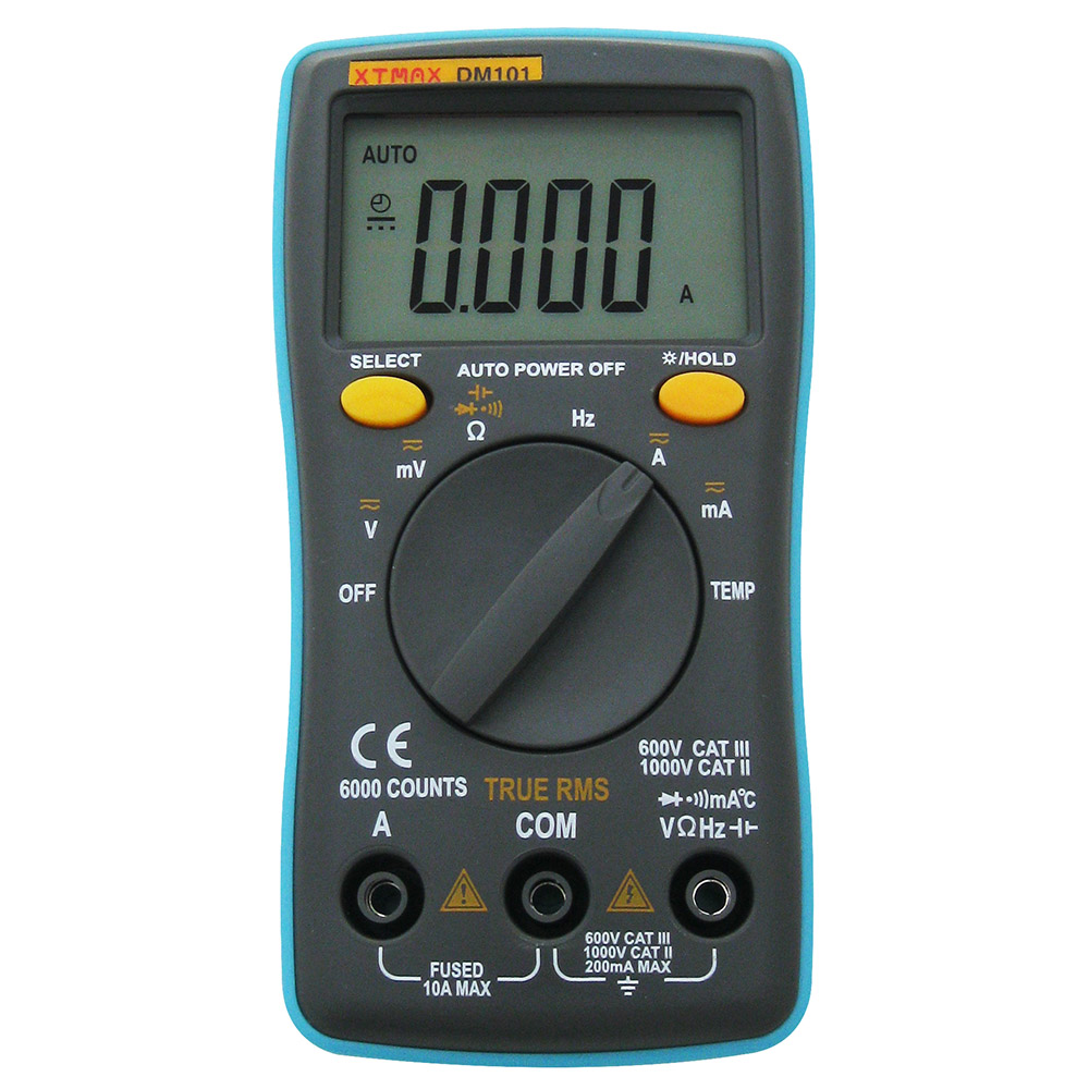
The one place the buzzer earns its keep is tracing a track or checking a fuse holder before you bother with the diode test. Use it to prove the connection, then switch the dial and take the measurement that actually answers the question. On the VC17B+ and the DM101 both functions sit on the same dial area, and the diode position is marked with the arrow and bar symbol described in our guide to the symbols on a multimeter dial.
Where the Reading Stops Being Useful
On a bare component the diode test is close to conclusive. On a board it is not, because every junction is surrounded by other paths that carry current. A reading of 0.02 V across a diode that sits across a transformer winding is measuring the winding, not the diode. A reading that looks correct in one direction and correct in the other can still belong to a part that fails only under load or only when warm.
The practical rule is to compare three things: the reading on the suspect part, the reading on the same part in the other direction, and the reading on a known good part of the same type measured the same way. When all three agree with the pattern in the table further up, the part is almost certainly fine, and the fault is somewhere the meter cannot reach while the board is assembled.
If the suspect part is an LED and the display shows a number well above 3.4 V, check the meter before the lamp. That reading is outside what any common LED produces, and it usually means the leads are across two junctions in series, or the dial is in a mode that is not what it appears to be.
What We Check Before a Meter Leaves the Factory
A diode test is only as good as the current source behind it, and that source is part of what we verify on every production run. The meters we build with a diode position, including the VC17B+ and the DM101, are checked against a reference junction at incoming inspection and again after calibration, because a drifting test current shifts every reading on that position by the same proportion.
If you are choosing a meter for a workshop that tests LEDs, tell us the colour and the typical forward voltage you need to resolve. The compliance of the diode test is not always printed on a datasheet, and it decides whether the instrument can test the parts your technicians actually handle. Engineers at our factory in Wenzhou will confirm the figure on a sample unit and send the reading with the part number, so the choice is made on a measurement rather than on a symbol on the dial.
Send us the reading you are seeing, the direction it was taken in, and the part number, and our engineering team will tell you whether the number belongs on the good side of that table or the bad side. That reply usually arrives the same working day from the Wenzhou office.