

How to Test Continuity with a Multimeter: Beep and OL Explained
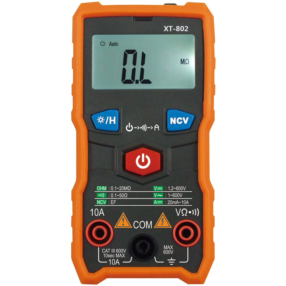
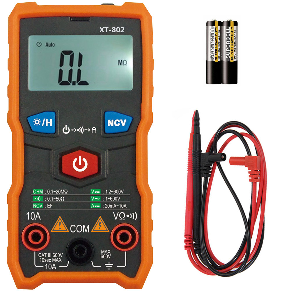
A continuity test answers one question: is there a complete path between the two probes? The meter beeps when the resistance between them is below a threshold the meter itself decides, shows OL when nothing conducts at all, and shows a number when something conducts but not perfectly. That number is the part most people ignore, and it is the part that separates a joint that is fine from one that is about to fail. The XT802 carries a continuity range printed on its panel from 0.1 to 50 ohms, and that upper figure is the whole story of what the beep does and does not tell you.
Everything below comes from the continuity and resistance specifications printed on our own instruments and from our production specification sheets. Wenzhou Zhengyuan Electronic Co., Ltd. builds these meters in its Wenzhou factory.
How to Run a Continuity Test
Power the circuit down, disconnect it from any source, and discharge anything still holding a charge before a probe goes anywhere near it, because continuity mode is a resistance measurement and a live circuit will give you a meaningless number at best. Turn the dial to the continuity position, then touch the two probe tips together first. A good pair of leads reads under about 0.2 ohms and beeps; anything higher means you are about to measure your leads instead of the conductor.
With the circuit dead and the leads proven, isolate the section you care about. Any parallel path around the component registers as continuity, so a blown fuse sitting in a populated board will beep through everything else and read as healthy; lift one end, or test the part out of the circuit. Place one probe on each end of the conductor, hold them still, and read two things at once: whether the meter beeps, and what number it shows. A beep with a reading under an ohm is a sound connection. A beep with a few ohms is a connection with contact resistance somewhere, and the terminals are the first suspect. OL with no beep is an open, and the job becomes finding where. If the reading flickers between OL and a number, keep the probes where they are and flex the harness or wiggle the joint, because an intermittent fault only shows up while something is moving.
What Each Continuity Reading Tells You
The table is a decision aid, not a tolerance table. Read the display, find the row, and take the action in the third column before you reach for a replacement part.
| What the display shows | What it means electrically | What to do next |
|---|---|---|
| Beep, reading below 1 ohm | A closed path with negligible resistance | The conductor and both probe contacts are good. Move on to the next leg of the circuit. |
| Beep, reading of a few ohms | Closed, but with contact resistance somewhere | Re-seat the probes, then clean the terminals. Condemn the part only once the reading survives a clean contact. |
| No beep, steady number in kilohms or megohms | Not open, but something resistive is in the path | You are measuring through a component, a damp joint or a burnt contact, not through a wire. Isolate and re-measure. |
| OL, no beep | Open circuit between the probes | The break is somewhere in the path. Split the path in half and test each half. |
| Reading flickers between OL and a number | An intermittent connection | Flex the harness or wiggle the joint while you watch the display. A steady probe position will never show this fault. |
The beep is a go/no-go signal produced by comparing the measured resistance against a fixed threshold inside the meter. It is not a pass mark and it is not a measurement, which is why the second and third rows are where continuity testing earns or loses its money.
What the Meter Is Actually Doing
In continuity mode the meter pushes a small known current out through the probes, measures the voltage that comes back, and displays the resulting resistance. An internal threshold decides whether that result produces a tone. The procedure is the same as any other resistance measurement, and the basic multimeter procedure covers probe placement and range selection, but the threshold is specific to the model in your hand. That is why two meters can disagree about the same joint without either of them being broken.
On the XT802 the continuity range is printed as 0.1 to 50 ohms. A joint measuring 30 ohms will beep on that instrument. The same joint, measured on a meter whose threshold sits at 10 ohms, stays silent and looks like an open circuit. Neither instrument is wrong; they are answering slightly different questions, and a technician who does not know their own threshold cannot tell the two answers apart.
Why the Continuity Range Is Not a Measurement
A continuity range is deliberately wide and deliberately approximate, because its job is speed on long runs of cable where all you need to know is whether a conductor is continuous end to end. Fifty ohms is a reasonable upper bound for that job and a useless one for judging whether a contact will carry ten amps, since a joint measuring 30 ohms will dissipate real power and heat up under load.
When the actual resistance matters, change the function. The DT6222 measures resistance from 400 ohms to 40 megohms at plus or minus 1.2 percent, which is enough resolution to watch a contact degrade from 0.05 ohms to 0.5 ohms over successive services. That trend, and not the beep, is what predicts a failure before it happens.
Continuity Against Diode Test
The diode symbol sits next to the continuity symbol on most dials because both use the same probe polarity and a similar test current, and the two functions are routinely confused. Continuity tells you whether current can flow. A diode test tells you how much voltage it costs to make current flow, by displaying the forward voltage drop. A shorted diode reads as continuous on both functions and looks perfectly healthy on one of them.
If the circuit contains a semiconductor, a rectifier, a freewheel diode or a transistor junction, the diode test position is the correct function, and the number it returns has a meaningful expected range: roughly 0.3 to 0.7 volts for a forward-biased silicon junction, and OL in the reverse direction. A continuity beep carries none of that information at all.
Where Continuity Testing Goes Wrong
The most common error is testing in circuit. Any parallel path around the component under test registers as continuity, so a blown fuse sitting in a populated board will beep through the rest of the circuit and read as good. Lift one end of the component, or test it out of the circuit, before drawing a conclusion about it.
The second most common error is trusting the leads. Probe contact resistance and the resistance of a long, worn test lead both sit in series with the measurement, and either can push a marginal joint across the threshold in either direction. When a reading looks surprising, touch the two probe tips together first. A good pair reads under 0.2 ohms, and anything higher means you are measuring the leads rather than the joint. The same discipline applies when you test a fuse or a circuit breaker, where a beep through a parallel path is the classic false pass.
Choosing a Meter by Its Continuity Range
If continuity checking is a large part of the work, the threshold is the specification worth reading. A wide band such as 0.1 to 50 ohms is fast for cable runs and for spotting opens, and it will beep on joints that a stricter meter rejects. A narrow band is stricter and misses fewer marginal joints, at the cost of more re-checks. Neither is better in the abstract; the mistake is not knowing which one is in your hand.
The multimeter symbols guide covers the rest of the dial positions and what each of them expects you to connect. For a production line or a distributor’s catalogue, the useful question is which of the two behaviours your customers’ work actually needs, and that is a question about the jobs they take on rather than about the instrument.
Send Us the Readings You Took
If you are selecting meters for a workshop, a production line or a distributor’s range, order a sample and run a known-good joint and a known-marginal joint through it, then tell us which one the meter called correctly. Send us the readings you took, what your customers actually use the meter for, and the quantity you are planning. Our Wenzhou engineers reply within 24 hours, confirm whether the XT802 or the DT6222 fits the line you are building, and quote per-unit pricing once we have your numbers.